 TRIM home
Modifications
Do you have an industrial / Heavy vehicle that does not quite meet your requirements, or need it to do more than it was designed to ? Then you have come to the right place!! We at Trim Engineers pride ourselves in our vast knowledge of Heavy Vehicle electronic, pneumatic, hydraulic control and systems. So if you need your vehicle to do something extra contact us and we will be able to help. All modifications carried out are done with operator safety in mind and are supplied with full instructions, parts lists and diagrams.
We can modify:
Contact:
email: service@trimengineers.co.uk
Tel: +44 (0) 1684 311346
![]()
An example s of recent modifications:
Enabling a customer to invert his steering on a port ro-ro tug with a rotating drivers console:
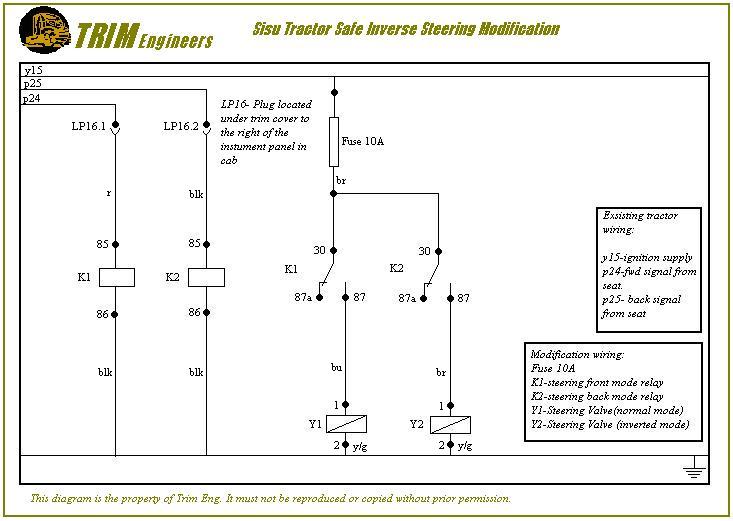
SISU TRACTOR SAFE STEERING INVERSION MODIFICATION
To safely invert steering direction, when the driver’s seat is rotated to the rear facing position, we have to insure the characteristics of the original system are maintained.
The original steering system utilizes an orbitrol type steering control fed via a hydraulic gear type pump. If the hydraulic pump fails or engine/transmission power fails, then the orbitrol control acts as a small pump enabling the operator to steer, although the steering at this point would be very heavy.
The orbitrol control valve has four main ports, Pressure (from pump), Tank return, A (left side of steering cylinder), B (right side of steering cylinder). Under normal operating conditions when the valve is turned to the left via the steering wheel the pressure will flow through to the left side of the cylinder through port A with the displaced oil from the right side of cylinder returning to tank via port B.
The easiest way to invert the steering would be to swap the hoses to the cylinder, so when you turn the valve to the left the cylinder would steer to the right, giving you the correct steering for rear facing position. This is fine until the operator turned the seat to the forward facing position.
To overcome this problem we need to be able to swap the steering between two modes a front steering mode (axle turns to the right when steered to the right) and a back steering mode (axle turns to the left when steered to the right)
To gain a front and rear mode we need:
A signal from the seat console indicating that the seat is locked mechanically in the rear or front facing position.
A valve to utilise the console signal, to change the direction of flow to the steering cylinder from the orbitrol control
The tractor has a front and back mode signal, as the gear change already inverts when the seat console is turned.
Utilizing this signal, a double solenoid hyd control valve needs to be used with a ‘straght through flow P-A, T-B’ when sol1 energized. When sol2 energized a ‘crossed flow P-B T-A’
The modification consists of two relays, signaled by the console position switch, which supply the double solenoid valve. The double solenoid valve is bolted underneath the cab floor and is piped between the orbitrol and the steering cylinders.
When the console is in the forward facing position then sol1 is energized by the console position ‘front’ switch via a relay, allowing oil to flow through the steering cylinders as normal. Sol2 is not energized.
When the console is in the rear facing position then Sol2 is energized by the console position ‘rear’ switch via another relay, which will swap the flow to the steering cylinders inverting the steering for the rear facing position. Sol1 is not energized.
To maintain the characteristics of the original system we mechanically lock the hydraulic valve in the last energized position. This is a safety precaution, if whilst the operator is driving the machine it has a fault and has electrical or engine/transmission failure the machine will still steer, although heavily, in same mode as before the failure occurred. Basically the steering is locked in a mode until the opposite mode is energized.
SISU TRACTOR SAFE STEERING INVERSION MODIFICATION KIT
Kit of parts to include:
| QTY | DESCRIPTION | COST | |
| 1 | Valve double solenoid | ||
| 1 | Sub plate | ||
| 1 | Sub plate mtg bracket | ||
| 4 | M6x60mm bolts and nuts | ||
| 4 | ½ bsp – ¾ JIC straight adapter | ||
| 2 | 1m 1/2" hydraulic hose with 90 ¾ JIC elbows | ||
| 1 | Wiring harness assy to include 2 relay and bases and screws. All plugs and sockets and cable pre wired and terminated ready for installation. Also instruction drawing. | ||
|
TOTAL COST |
|||
![]()
Enabling a customer to meet health and safety requirements by, putting an alarm in the tugmaster to warn operator when park brake is not applied if he leaves the cab.
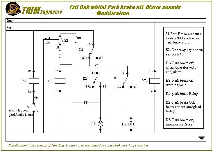
MODIFICATION: Park Brake Left Off by operator/driver warning alarm
Problem: Drivers or operators leaving the Tugmaster cab with the park brake left off.
Solution: If the park brake is not set, on exiting the cab of Tugmaster the driver/operator hears an alarm to remind him to apply the parking brake. Once the park brake is set alarm is switched off. The alarm needs to operate whether the ignition is switched on or off and the park brake is not set. The park brake on warning lamp should only operate when ignition is switched on.
Action: At present a normally closed park brake switch is used to switch on the park brake warning lamp on the dash board when the ignition is on. This circuit will be modified to control the original warning lamp and the added park off warning alarm.
To modify the circuit to do what is required the following action is required:
1. park brake switch needs to be changed to a normally open type.(S1)
2. A light beam sensor (photoelectric cell) needs to be fitted across the door aperture.(S2)
3. Three relays need to be added to the junction box. (K1,K2,K3)
4. Warning alarm needs to be fitted into the cab.
The first relay K1 switches the alarm circuit on or off by means of a signal from the park brake switch.(S1)
The second relay K2 is energized when the door beam sensor (S2) is triggered, and its supply comes from Relay K1 when the park brake is off. When K2 is energized the supply will be switched to sound the alarm (H1) and also to hold the alarm on even if the door sensor (S2) is no longer triggered. The alarm will only then be switched off by switching off K1 which is done by applying the park brake.
The third relay K3 switches on the park brake warning lamp (H2) when the ignition is on and the park brake is on. K3 is switched on by ignition. The supply to K3 comes from K1 when the park brake is on K3 then supplies the park brake on warning lamp (H2).
Please refer to drawing attached for wiring circuit.
service modification sales SpareParts recovery hire vacancies video home